
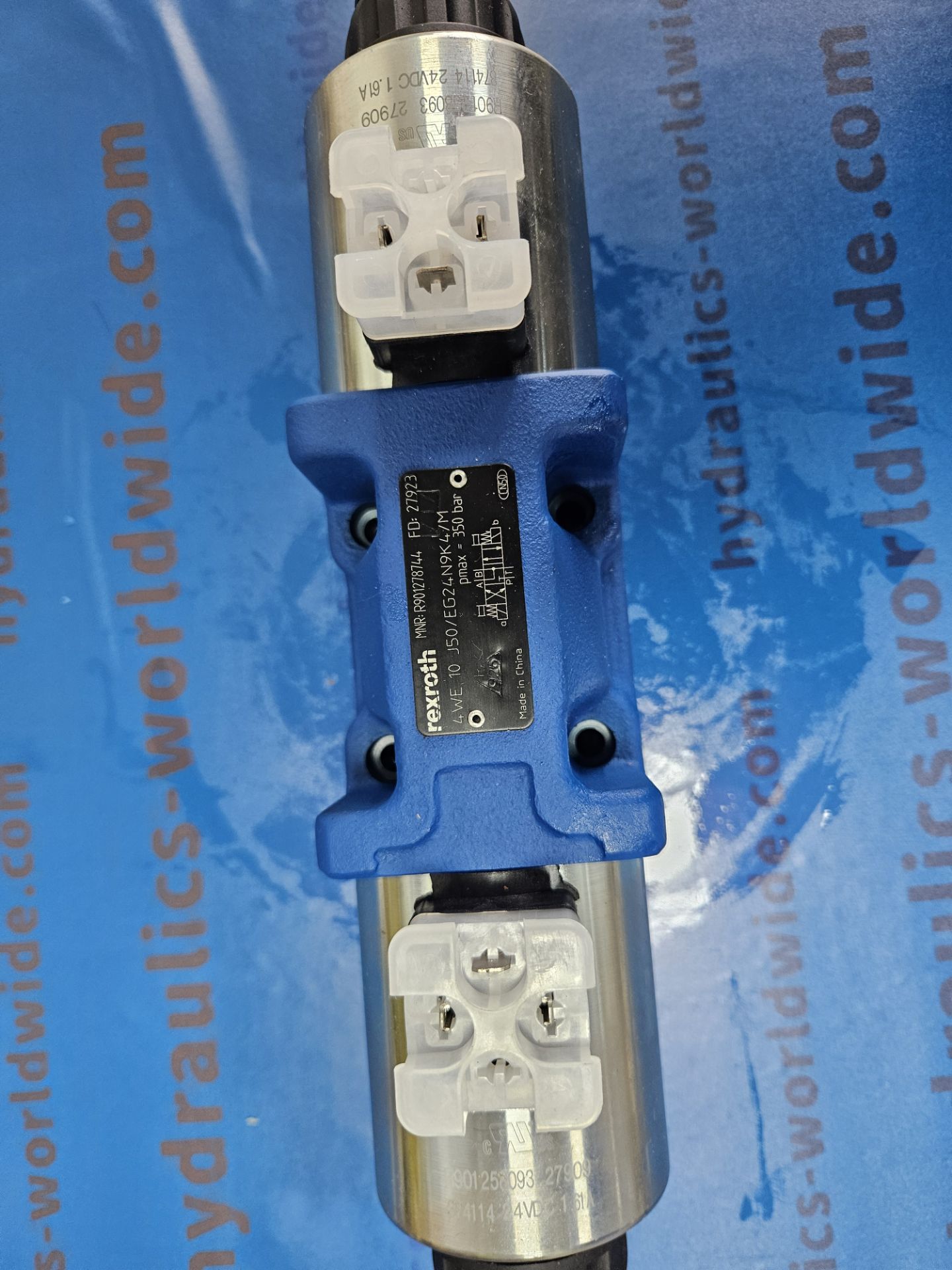
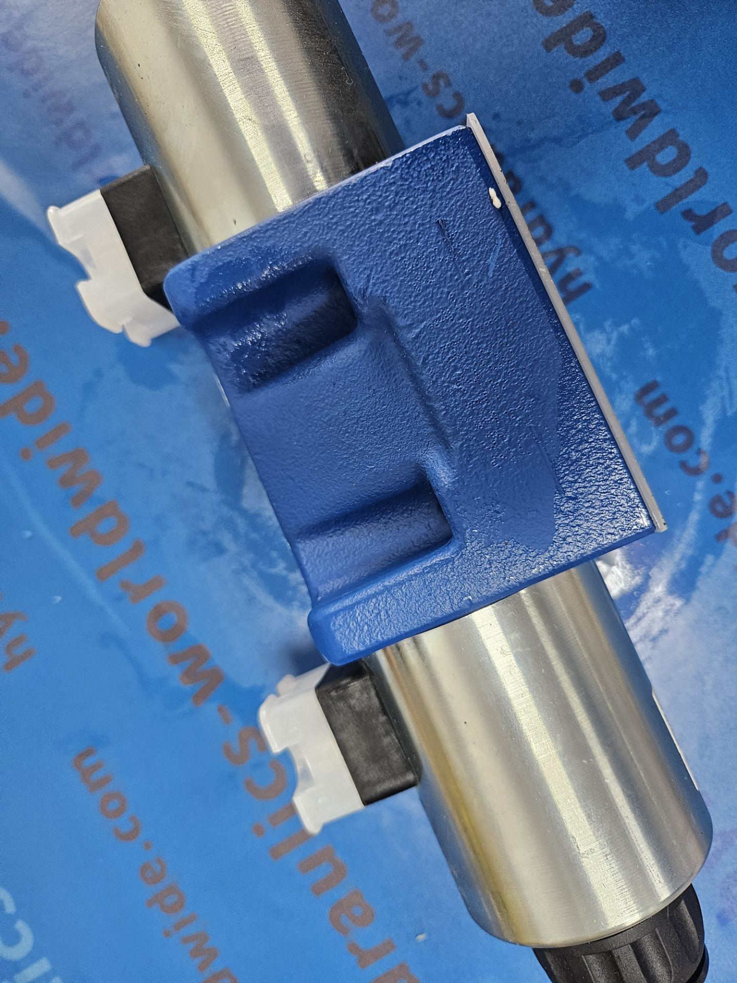
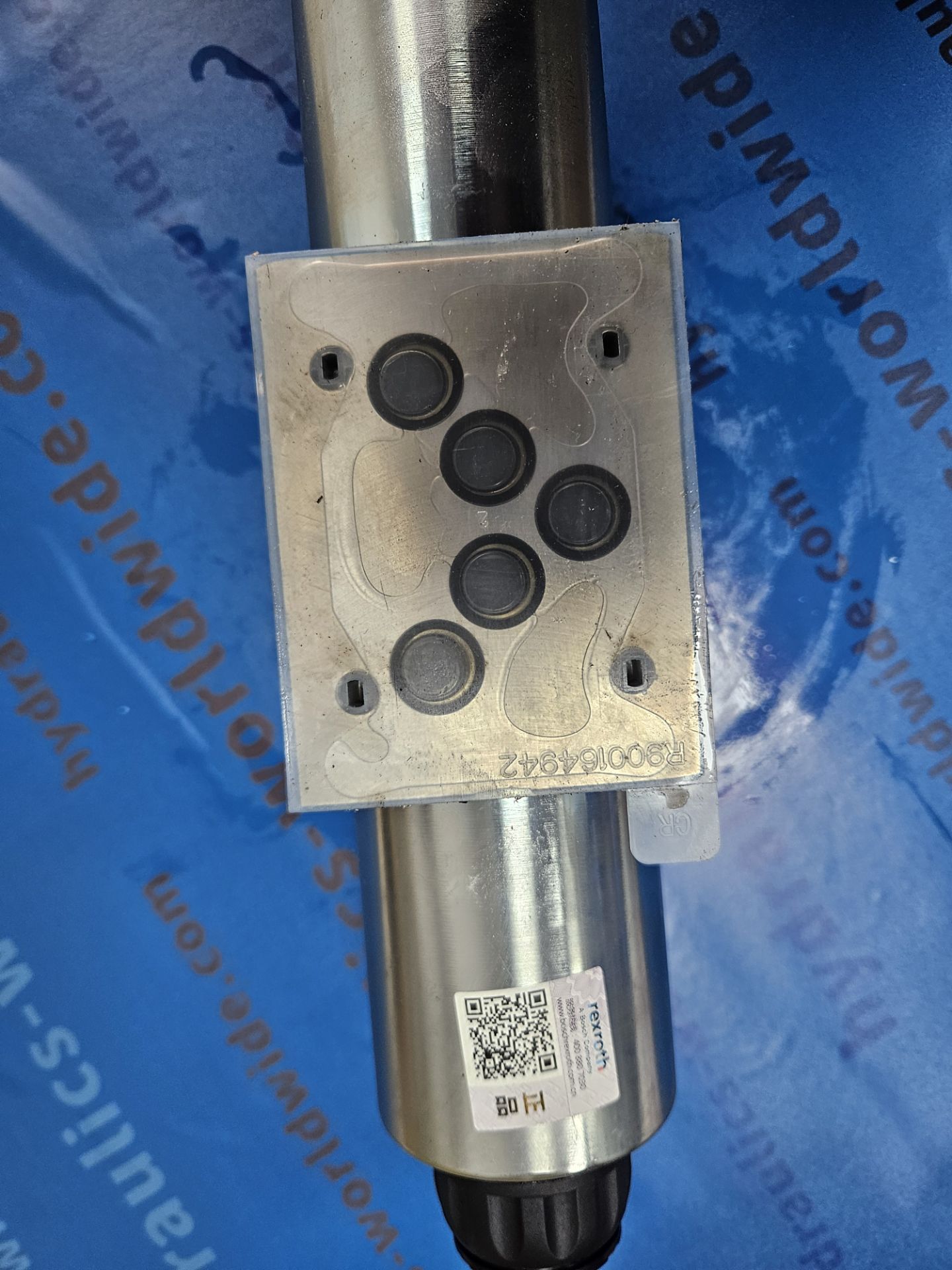
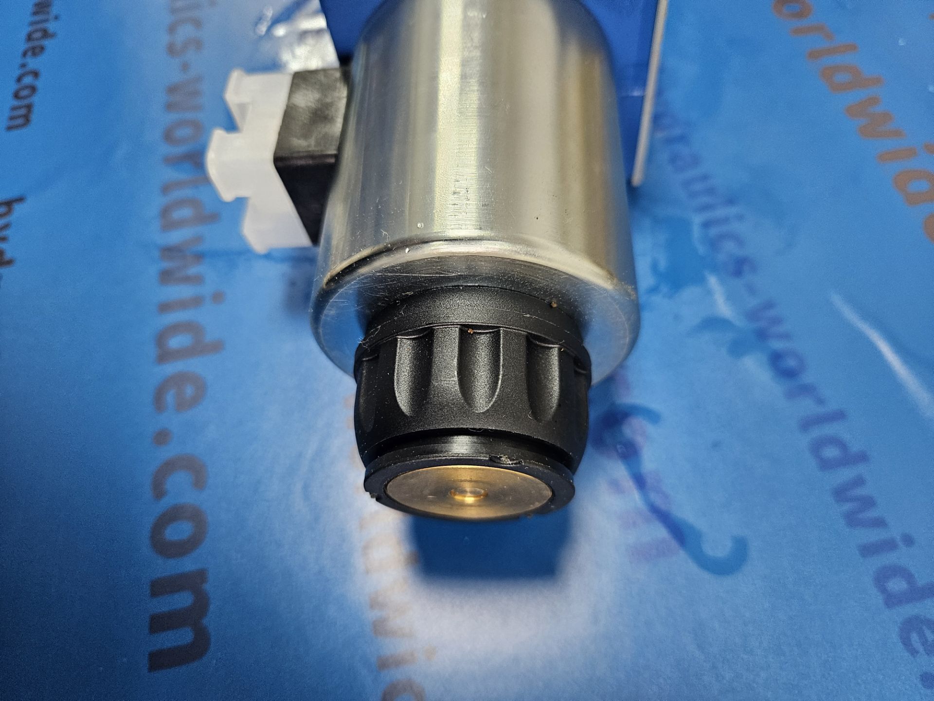
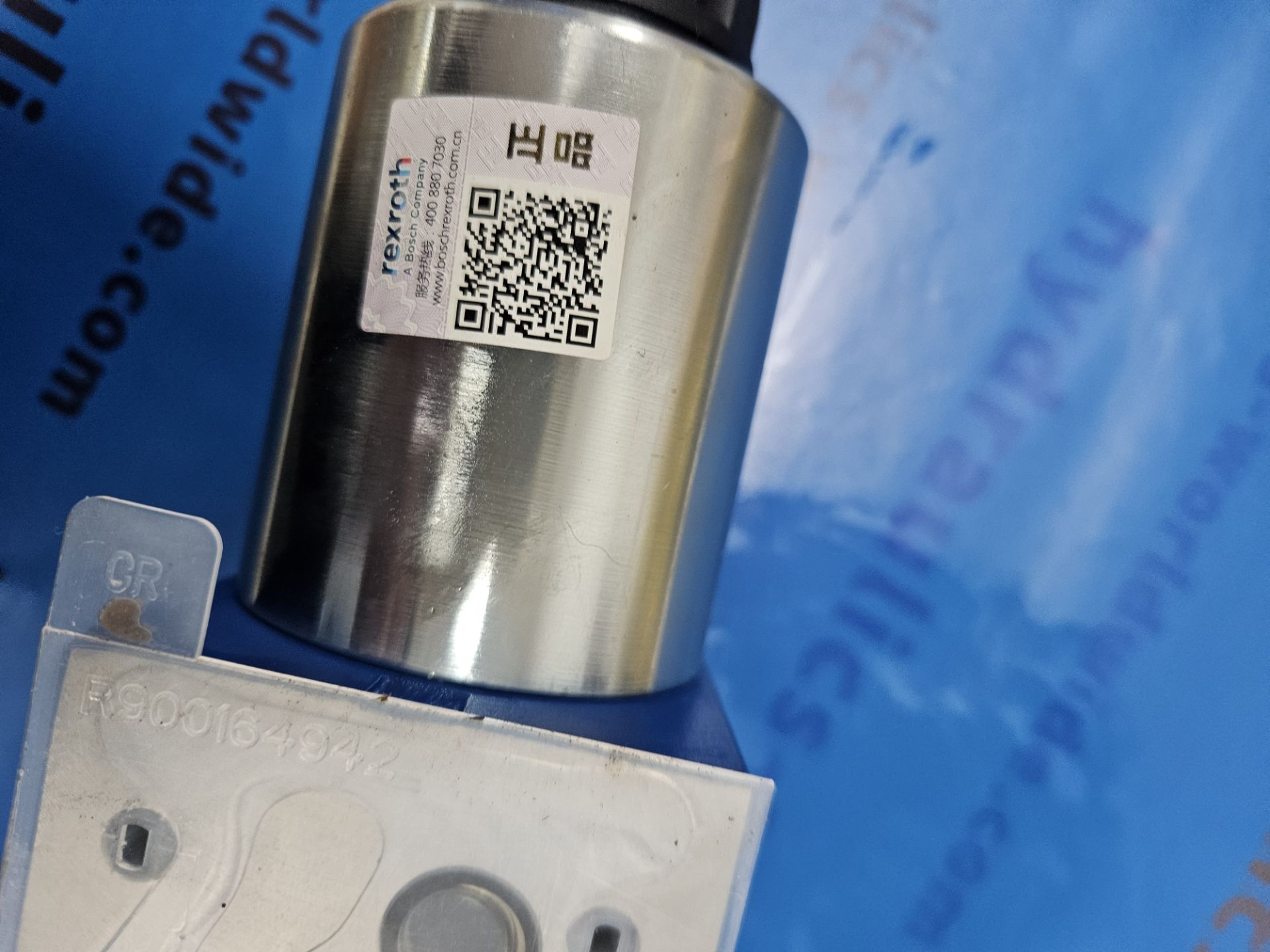
DIRECTIONAL SPOOL VALVE 4WE10J5X/EG24N9K4/M
R901278744
Size 10, symbol J, solenoid-actuated, 24 V DC
Shipped in 5 business days from Lohr, DE, if ordering a maximum of 10pc
Estimated transport time to Austria: 2 days
Industrial hydraulic valve in a high performance range. Reliable switching of the oil flow direction according to hydraulic symbol.
- Spool valve
- Direct actuated
4WE10J5X/EG24N9K4/M R901278744 4WE10J50/EG24N9K4/M
| Product attributes | |
|---|---|
| Connection diagram | ISO 4401-05-04-0-05 |
| Product family | WE10../E |
| Max. pressure [bar] | 350 |
| Max. flow [l/min] | 150 |
| Spool symbol | Symbol J |
| Type of connection | Subplate mounting |
| Size | 10 |
| Type of actuation | with solenoid actuation |
| Number of ports | 4 |
| Number of switching positions | 3 |
| Supply voltage | 24 VDC |
| Electrical connector | Connector 3-pole (2 + PE) |
| Electrical connection description | Connector 3-pole (2 + PE) according to EN 175301-803 |
| Hydraulic fluid | HL,HLP,HLPD,HVLP,HVLPD,HFC |
| Seals | NBR |
| Weight [kg] | 5.43 |
4WE10J50/EG24N9K4/M REXROTH 4WE10J5X/EG24N9K4/M R901278744 REXROTH
4/3-, 4/2- or 3/2-way version
Porting pattern according to ISO 4401-05-04-0-05
High-power solenoid, optionally rotatable by 90°
Electrical connection as individual or central connection
Cartridge optionally equipped with PWM connector
(fast switching amplifier, energy reduction)
Manual override, optional
CE conformity according to the Low-Voltage Directive
2014/35/EU for electrical voltages > 50 VAC or > 75 VDC
Solenoid coil as approved component with
UR marking, optional
Approval according to CSA C22.2 no. 139-13, optional
Hydraulic valves for industrial applications Data sheet 07600-B
Subplates Data sheet 45100
Hydraulic fluids on mineral oil basis Data sheet 90220
Environmentally compatible hydraulic fluids Data sheet 90221
Flame-resistant, water-free hydraulic fluids Data sheet 90222
Flame-resistant hydraulic fluids – containing water (HFAE, HFAS, HFB, HFC) Data sheet 90223
Connector switching amplifier type VT-SSBA1 Data sheet 30362
Directional spool and seat valves with electrical actuation and M12x1 plug-in
connection
Data sheet 08010
Reliability characteristics according to EN ISO 13849 Data sheet 08012
CE declaration of conformity according to Low-Voltage Directive 2014/35/EU upon request
Information on available spare parts www.boschrexroth.com/spc
Accessories (separate order)
Mating connectors and cable sets
Pos. 1) Designation Version Short designation Material
number
Data sheet
7, 11 Mating connector;
for valves with “K4” connector,
2-pole + PE, design A
Without circuitry, M16 x 1.5, 12 … 240 V, “a” Z4 R901017010 08006
Without circuitry, M16 x 1.5, 12 … 240 V, “b” R901017011
Without circuitry, NPT 1/2″, 12 … 240 V, “a” Z45 R900004823
Without circuitry, NPT 1/2″, 12 … 240 V, “b” R900011039
With indicator light, M16 x 1.5, 12 … 240 V Z5L R901017022
With indicator light, NPT 1/2″, 12 … 240 V Z55L R900057453
With rectifier, M16 x 1.5, 80 … 240 V RZ5 R901017025
With rectifier, NPT 1/2″, 80 … 240 V RZ55 R900842566
With indicator light and Z-diode-suppressor,
M16 x 1.5, 24 V
Z5L1 R901017026
With indicator light and rectifier, M16 x 1.5,
80 … 240 V
RZ5L R901017029
With indicator light and rectifier, NPT 1/2″,
80 … 240 V
RZ55L R900057455
10 Mating connectors;
for directional valves with “C4”
connector (AMP Junior-Timer)
10 … 32 V, 5 A 2P JUNIOR D2 2 R901022127
10 … 32 V, 5 A 2P D1.2 JUNIOR R900313533
8 Mating connectors;
for sensors and valves with
“K24”, “K35” and “K72”
connectors, 4-pole
M12 x 1, angled, PG 7 4PZ24 R900779509
M12 x 1, angled, PG 7 R900082899
9 Cable sets;
for valves with two solenoids
(double mating connectors) and
connector “M12 x 1”
24 V, 4 A Z60 R901207825
With indicator light, 24 V, 4 A Z60L R901207824
With indicator light and Z-diode-suppressor,
24 V, 4 A
Z60L8 R901207823
With free line end, 230 V, 4 A, 3 m Z61 R901207826
With free line end, 230 V, 4 A, 5 m R901207892
15 Mating connectors;
for valves with central connection
with “DK6L” connector
250 V, 10 A, PG 11 7PZ6 R900002803
1) See dimensions page 23 … 26.
Function, section
Type .WE 10 E…
Throttle insert
The use of a throttle insert is required when, due to
prevailing operating conditions, flows occur during the
switching processes which exceed the performance
limit of the valve.
The directional valves of type WE are solenoid-actuated
directional spool valves that can be used as
electro-hydraulic component. They control the start,
stop and direction of a flow.
The directional valves basically consist of the
housing (1), one or two electronic solenoids (2),
the control spool (3), and the return springs (4).
In the de-energized condition, the control spool (3) is
held in the central position or in the initial position by
the return springs (4) (except for version “O”).
If the wet-pin electronic solenoid (2) is supplied with
power, the control spool (3) moves out of its rest
position into the required end position. In this way,
the required direction of flow according to the selected
symbol is released.
After the electronic solenoid (2) has been switched off,
the control spool (3) is pushed back into its central
position or into its initial position (except for valves
with “OF” detent and valves without type “O” spring).
A manual override (5) allows for the manual switching of
the valve without solenoid energization.
For unobjectionable functioning, the hydraulic system
has to be bled properly.
Without spring return “O” (only possible with
symbols A, C and D)
This version is a directional valve with two spool
positions and two electronic solenoids without detent.
The valve without spring return at the control spool (3)
has no defined basic position in the de-energized
condition.
Without spring return with “OF” detent
(only possible with symbols A, C and D)
This version is a directional valve with two spool positions
and two electronic solenoids with detent. The detents are
used to fix the control spool (3) in the relevant spool
position. During operation, continuous application of
current to the electronic solenoid can thus be omitted
which contributes to energy-efficient operation.
Version “.73…A12” (smooth switching behavior)
By means of structural design of the control spools and
solenoids, switching shocks occurring when activating
and deactivating the valves are significantly reduced.
The switching shocks, measured as acceleration values a,
can be reduced by up to approx. 85% when compared to
the standard valve depending on the design of the control
spool (for this, see “Acceleration values” on page 14).
Notice:
Pressure peaks in the tank line to two or several
valves can result in unintended movements of the
control spool in the case of version with detent.
We therefore recommend that separate return lines be
provided or a check valve installed in the tank line.
Due to the design principle, internal leakage is
inherent to the valves, which may increase over the
life cycle.
Details
| Weight | 6 kg |
|---|---|
| Dimensions | 27 × 15 × 15 cm |


Reviews
There are no reviews yet.