


AZPW-21-022RQRXXMB-S0593 is the primary model keyword for this Bosch Rexroth hydraulic gear pump; the corresponding material number is R983032285. External hydraulic gear pump identified by the complete AZPW ordering code and material number. This page is organized for engineers, maintenance teams and industrial buyers who need to identify the exact component before requesting price, stock or delivery information.

The complete code matters. Similar-looking hydraulic components can differ in size, spool or function, pressure range, electrical option, seal material, mounting interface or special version. Use AZPW-21-022RQRXXMB-S0593 together with R983032285 when comparing the nameplate, photographs, machine records and purchase documents. A match on only one portion of the code is not a complete interchangeability decision.
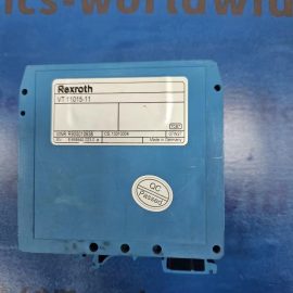
Our product photographs show the supplied unit from several angles. They are intended to support identification, receiving inspection and quotation review. Final application approval remains the responsibility of the system designer or qualified hydraulic engineer.
AZPW-21-022RQRXXMB-S0593 product overview
The AZPW-21-022RQRXXMB-S0593 hydraulic gear pump is identified on this page by Bosch Rexroth material number R983032285. For replacement sourcing, both identifiers should appear on the quotation and order acknowledgement. The model communicates the configured version, while the material number helps distinguish the exact catalog item from related variants.
Industrial hydraulic reliability depends on more than the brand name. The mounting pattern, pressure rating, flow requirement, actuation method, electrical supply, fluid compatibility and operating environment must agree with the machine design. When AZPW-21-022RQRXXMB-S0593 is being considered as a replacement, compare every available technical field and inspect the existing assembly for adapters, pilot components, connectors and special accessories.
AZPW-21-022RQRXXMB-S0593 key specifications
| Specification | Value |
|---|---|
| Brand | Bosch Rexroth |
| Product family | AZPW |
| Product type | External gear pump |
| Rotation | Use only the direction indicated on the pump |
| Ambient temperature with NBR seals | -30 to +80 °C |
| Fluid temperature with NBR seals | -30 to +80 °C |
| Continuous viscosity range | 12 to 800 mm²/s |
| Recommended continuous viscosity | 20 to 100 mm²/s |
| Cold-start viscosity, maximum | 2000 mm²/s |
These identification details summarize the product information associated with R983032285. Confirm the latest technical documentation and the complete nameplate before installation. If a specification is application-critical, include it in the inquiry so that the offered configuration can be checked against the duty point.
7 proven AZPW-21-022RQRXXMB-S0593 selection checks
1. Match the full model code
Compare AZPW-21-022RQRXXMB-S0593 character by character. Series designations, option letters, voltage codes and special suffixes are functional information, not formatting. A shortened code may point to a family instead of the exact R983032285 configuration.
2. Confirm the material number
Use R983032285 as the secondary cross-check. If the model and material number do not agree across the nameplate, documentation and quotation, stop the selection process and resolve the discrepancy before ordering.
3. Verify the hydraulic interface
Check the port or mounting pattern, nominal size, sealing arrangement and installation envelope. Photograph the existing mounting surface when practical. Never assume that two hydraulic gear pump variants share the same interface because their housings look alike.
4. Review pressure and flow duty
Compare the machine working pressure, transient pressure and required flow with the permitted values for AZPW-21-022RQRXXMB-S0593. Consider the complete circuit and the expected operating cycle. Pressure loss, heat generation and dynamic response may matter even when static dimensions match.
5. Check actuation and electrical details
Where an electrical or pilot function is present, confirm supply voltage, connector, command electronics, coil option, wiring and control logic. For mechanical products, confirm adjustment direction, locking method and access. Do not energize a replacement until the control data is verified.
6. Confirm fluid, seal and environment compatibility
Hydraulic fluid type, viscosity, cleanliness, temperature, ambient conditions and seal material influence service life. Review the machine fluid specification and maintenance standard before commissioning AZPW-21-022RQRXXMB-S0593. Contamination control is especially important when old hoses or manifolds are reused.
7. Document the final configuration
Record AZPW-21-022RQRXXMB-S0593, R983032285, serial or production information, installation date and machine location. Attach clear photographs to the maintenance record. This creates a reliable baseline for future troubleshooting and reduces uncertainty during the next procurement cycle.
AZPW-21-022RQRXXMB-S0593 receiving, installation and commissioning checklist
Before unpacking, compare the carton and order references. After unpacking, inspect the product for shipping damage, corrosion, missing caps or plugs, damaged threads and contaminated ports. Compare the visible nameplate with AZPW-21-022RQRXXMB-S0593 and R983032285. Keep protective covers in place until the hydraulic lines or manifold are ready.
- Isolate, depressurize and lock out the hydraulic and electrical energy sources.
- Confirm that the mounting surface is clean, flat and free from old seal material.
- Use the specified seals, fasteners and tightening sequence for the interface.
- Prevent lint, metal particles and dirt from entering open ports.
- Confirm port identification and flow direction before connecting hoses or pipes.
- Check connector pin assignments and supply voltage before energizing.
- Start at a controlled setting and monitor pressure, leakage, noise and temperature.
- Retain the old unit until the replacement has passed functional verification.
A new AZPW-21-022RQRXXMB-S0593 component cannot correct unrelated circuit faults. If the original failure was caused by contamination, excessive pressure, cavitation, incorrect wiring or an unstable control signal, identify and correct the root cause before returning the machine to full duty.
AZPW-21-022RQRXXMB-S0593 application-fit guidance
AZPW-21-022RQRXXMB-S0593 should be selected for systems whose hydraulic and control requirements match its documented configuration. Typical industrial evaluation contexts include maintenance replacement, machine refurbishment, spare-parts planning, hydraulic power-unit service and OEM support. Suitability cannot be determined from photographs alone.
For a useful quotation, provide the full model, material number, required quantity, destination country and requested delivery date. Also include photographs of the nameplate and complete assembly. If the application is a retrofit rather than a like-for-like replacement, provide the circuit diagram, duty pressure, flow, fluid, temperature range and control signal.
AZPW-21-022RQRXXMB-S0593 frequently asked questions
What is the primary keyword for this product?
The primary product keyword is AZPW-21-022RQRXXMB-S0593. The secondary identifier is Bosch Rexroth material number R983032285.
Why should both identifiers be used?
The model describes a configured variant, while R983032285 is an additional item-level reference. Using both reduces the risk of quoting a related but different component.
Can AZPW-21-022RQRXXMB-S0593 replace any visually similar unit?
No. Visual similarity is useful for preliminary identification only. Verify the complete code, interface, hydraulic ratings, control option and environmental compatibility.
What information should be sent with an inquiry?
Send AZPW-21-022RQRXXMB-S0593, R983032285, quantity, destination, required date and clear photographs. For application review, add operating pressure, flow, fluid, temperature and control information.
Are the page photographs the actual product views?
Yes, the new photographs on this listing show the product from multiple angles for identification and inspection support. The images do not replace dimensional drawings or technical data sheets.
How should the component be stored?
Keep it clean, dry, capped and protected from impact and condensation. Follow the manufacturer guidance for preservation, storage time and recommissioning.
What should be checked after start-up?
Monitor leakage, pressure response, flow behavior, noise, temperature and control stability. Stop the machine if abnormal behavior is detected.
Where can official product identification be checked?
Review the Bosch Rexroth product reference for R983032285. For additional available products, visit our hydraulic products catalog or contact our sales team.
Maintenance and lifecycle planning
A reliable spare-parts plan treats the component as part of a hydraulic function, not as an isolated item on a shelf. Record the machine, circuit location, operating hours, failure history and environmental conditions. If the component is production-critical, define the acceptable outage time and compare it with the expected replenishment lead time. This helps determine whether one unit, a rotating spare or a larger safety stock is appropriate.
Storage practice affects readiness. Keep this component in its protective packaging in a clean, dry area with stable temperature. Protect exposed interfaces and electrical connections. Do not stack heavy material on the product, and use first-in/first-out control where storage-life guidance applies. Before a long-stored unit is installed, inspect the packaging, preservation condition, elastomer surfaces and visible metal parts.
Maintenance intervals should follow the machine risk and manufacturer guidance rather than an arbitrary calendar alone. Useful condition indicators include external leakage, slower response, pressure drift, unusual noise, rising temperature, unstable motion and increasing contamination counts. Trending these observations can reveal a developing circuit issue before the unit is blamed or replaced unnecessarily.
When a unit is removed, label all connections before disassembly. Cap hoses and ports immediately. Compare the removed product with the replacement side by side, including model code, R983032285, connector orientation, adjustment position and mounting details. Photograph both units and the clean interface. These steps create evidence if commissioning behavior differs from the original installation.
Hydraulic troubleshooting framework
Unexpected pressure or flow behavior
Start with measured system conditions. Confirm pump supply, relief settings, downstream restrictions, fluid temperature and commanded state. A symptom at this component may be caused by another circuit element. Compare the actual pressure and flow with the schematic and expected operating sequence before removing parts.
Slow, unstable or incomplete response
Check fluid viscosity, contamination, trapped air, pilot supply where applicable, electrical signal quality and mechanical loading. Inspect connectors and wiring without bypassing safety devices. If the issue changes with temperature, document cold-start and warm-running behavior because this can help separate hydraulic, electrical and mechanical causes.
External or internal leakage concerns
External leakage requires immediate attention. Identify whether fluid comes from a port connection, mounting interface, adjustment point or body joint. Clean the area and observe at a controlled pressure. Internal leakage assessment normally requires circuit measurements and the approved test method; visual appearance alone is insufficient.
Noise, vibration or heat
Noise and heat can originate from aeration, cavitation, excessive pressure drop, unstable control, misaligned piping or contaminated fluid. Verify oil level, suction conditions, filter state and return-line arrangement. Do not continue full-load operation until abnormal temperature or vibration has been understood.
Intermittent electrical operation
For electrically actuated configurations, measure the supply and command under load, not only with the connector unplugged. Check voltage, polarity, grounding, connector retention and cable condition. Compare the electrical option in the full configured code with the controller configuration. Intermittent faults should be documented with time, temperature, command and machine state.
A disciplined troubleshooting record prevents repeated part swapping. List each observation, measurement and change in chronological order. If the unit is sent for analysis, include the operating symptom, fluid condition and circuit context. A component returned with no application information is much harder to evaluate meaningfully.
Procurement and quotation checklist
Industrial buyers can reduce clarification cycles by sending a structured request. Put the full model in the subject line and R983032285 in the item description. State whether the requirement is for an exact replacement, a compatible alternative study, a repair evaluation or a new design. These are different scopes and require different technical evidence.
- Full Bosch Rexroth manufacturer and model reference.
- Material number: R983032285.
- Required quantity and whether partial shipment is acceptable.
- Delivery destination, requested date and preferred transport method.
- Clear nameplate, front, rear, side and interface photographs.
- Condition requested: new unit, replacement study or repair service.
- Machine manufacturer, equipment type and installation location.
- Any certificates, documentation or packaging requirements.
- For a retrofit, the hydraulic schematic and verified duty data.
- Contact details for technical clarification and commercial response.
When reviewing an offer, compare the quoted model and R983032285 with the request. Check quantity, condition, lead time, warranty terms, Incoterms, freight, taxes and validity. If the description abbreviates the model, request written confirmation of the complete code before approving the order.
Authenticity and identification review
Identification review should use several consistent signals: the model code, R983032285, manufacturer marking, production information, physical configuration and documented source. No single photograph proves every aspect of origin or application suitability. Treat unclear or conflicting markings as a reason for further verification.
High-resolution photographs are especially useful for remote quotation review. The nameplate should be readable without aggressive image enhancement. Overall views should show the body, ports, connectors and adjustment features. Interface photographs help identify the mounting pattern but should not be used as a substitute for dimensional documentation.
Packaging and labels may change over time, so avoid rejecting or approving this model based only on cosmetic differences. Technical identifiers and a traceable commercial record are more useful. If documentation requirements are mandatory for your project, state them before the order is placed.
System documentation recommendations
Update the machine bill of materials after installation. Record the complete model, R983032285, purchase order, supplier, commissioning date and the reason for replacement. Link the record to the hydraulic schematic and store the new product photographs with the maintenance history. This makes future identification faster and supports root-cause analysis.
For multi-site operations, use a consistent naming convention for stock locations and computerized maintenance records. Avoid informal abbreviations that remove functional characters from the full code. Barcode or QR labeling can point technicians to controlled documents while the human-readable model and material number remain visible.
After commissioning, capture baseline measurements appropriate to the circuit. Depending on the product and machine, this may include pressure, flow, response time, leakage, temperature, current or command signal. Baseline data gives maintenance teams a meaningful comparison when performance changes later.
Fluid cleanliness and preventive-care notes
Clean fluid is a system requirement, not merely a component preference. Dirt introduced during hose changes, reservoir work or uncapped storage can damage precision surfaces and create symptoms that appear after a new unit is installed. Use clean tools, capped containers and filtered transfer equipment. Do not wipe open ports with cloth that can shed fibers.
Before installation, review the latest oil analysis or contamination record where available. Investigate water, oxidation products, metal wear particles and filter bypass events. If a previous component failed catastrophically, flushing only the immediate connection may be inadequate. The reservoir, lines, manifolds, actuators and coolers may retain debris that can circulate back to the replacement.
Filter selection and condition should match the machine design. A filter with the correct nominal size but an unsuitable efficiency, collapse rating or bypass setting may not provide the intended protection. Record filter part numbers and differential-pressure observations during commissioning. Replace elements according to condition and approved maintenance practice rather than automatically assuming that a new-looking element is clean.
Temperature control also supports reliability. Excessive temperature reduces viscosity and accelerates fluid aging, while very low temperature can raise pressure drop and delay response. Monitor actual operating temperature after installing the replacement, particularly during the longest and heaviest production cycle. Compare the result with the normal machine baseline.
Inspect external connections after the first controlled run and again after the machine reaches normal temperature. Do not tighten fittings under pressure. Any retightening must follow the approved procedure and torque guidance. A clean inspection surface makes small leaks easier to detect and prevents old residue from being mistaken for a new problem.
Preventive care should also include connector protection, cable strain relief, mounting-fastener checks where permitted, and observation of unusual sound or movement. Avoid unauthorized adjustment. If the product has an adjustable setting, document the verified commissioning value and the person responsible for approval.
Finally, retain a representative oil sample and commissioning notes when the failure consequence is significant. These records provide context if performance later changes. They also help distinguish a product issue from contamination, application overload or an upstream system fault.
Request a product quotation
Contact us with the complete model and R983032285 for price, availability and delivery review. The most efficient inquiry includes the full identifiers and clear product photographs. For urgent maintenance, state the machine status and required delivery deadline so the request can be prioritized correctly.
Details
| Weight | 7.5 kg |
|---|---|
| Dimensions | 20 × 20 × 20 cm |


Reviews
There are no reviews yet.